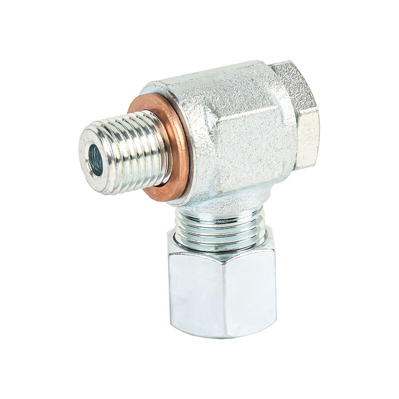
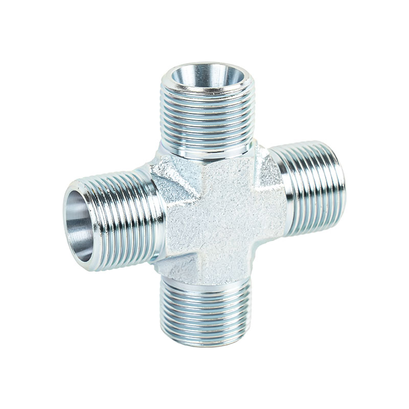
Joint body
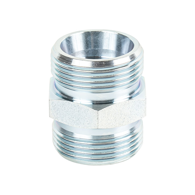
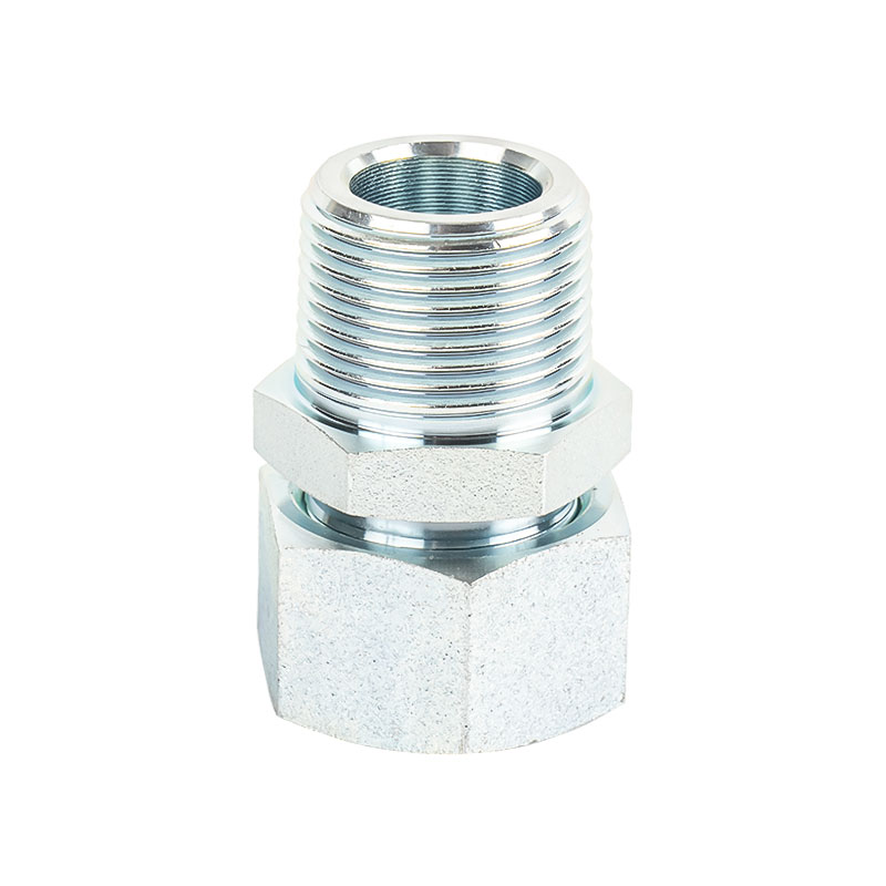
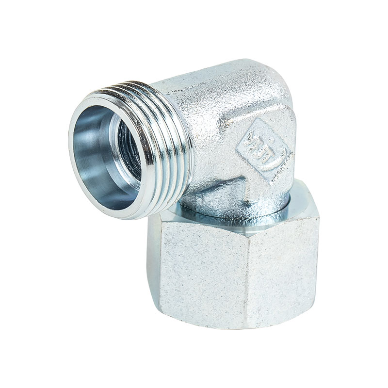
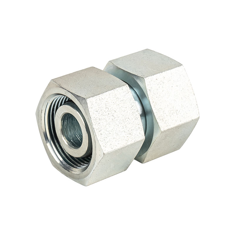
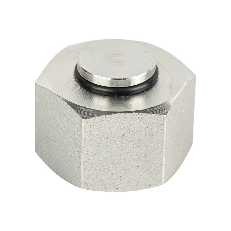
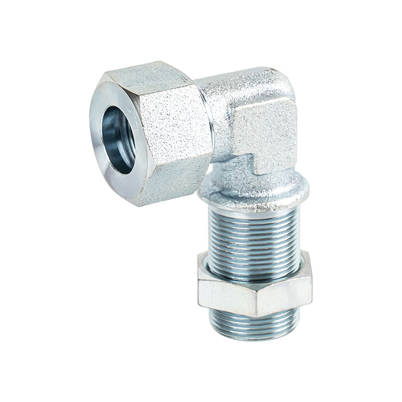
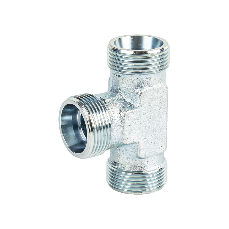
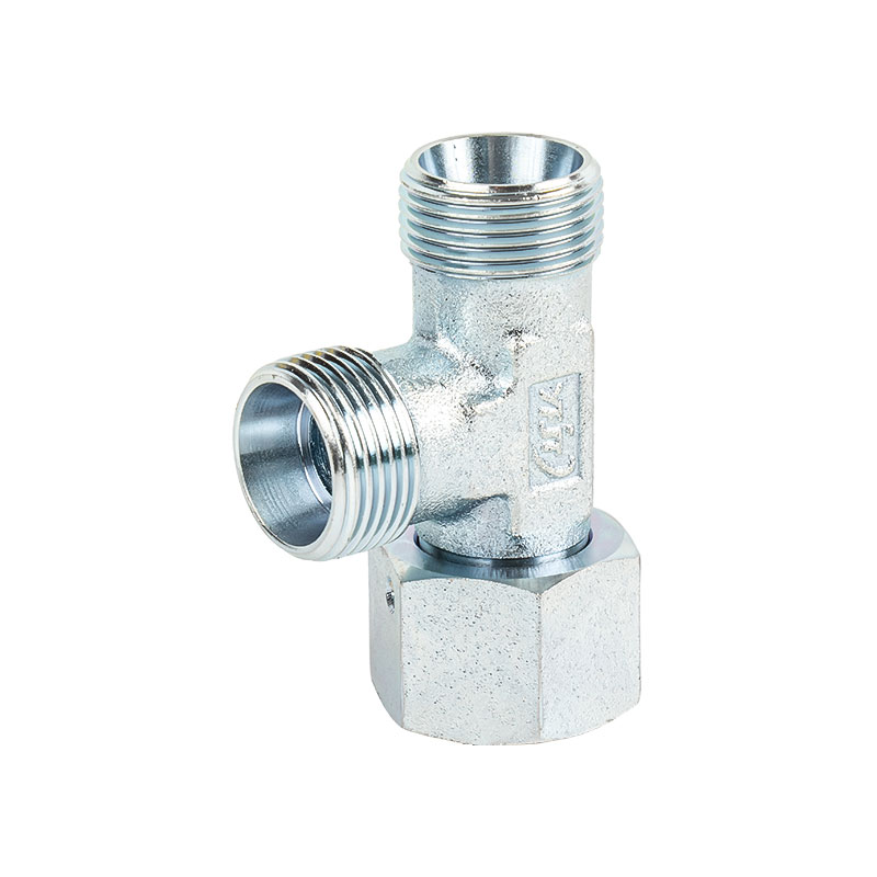
The joint body is the core part of the withhold hose joint, which is directly connected to the pipe or equipment interface in the system. One end is inserted into the hose, usually with a special structure to enhance the fixing force, such as barbs, annular grooves, cones, etc.; the other end is connected to the external system by external threads, internal threads, flanges, welding, etc. The material of the joint body is mostly carbon steel, stainless steel or brass to meet the pressure resistance, corrosion resistance and fatigue resistance requirements in different use environments. This part bears the main mechanical strength of the entire joint and plays an important role in guiding and sealing in the connection.
Sleeve part
The sleeve is a metal ring-shaped part wrapped around the outer wall of the hose, and the deformation area during the withholding process is mainly concentrated here. The internal structure of the sleeve usually has several serrated or diamond-shaped mesh patterns to enhance the friction between the outer wall of the hose. Its outer surface is designed to be suitable for the clamping of the withholding machine mold. During withholding, the sleeve is deformed by the pressure of the hydraulic press, so that the hose and the joint body are tightly pressed together. The material is generally low-carbon steel or medium-carbon steel with strong plasticity, and sometimes the surface is galvanized, electrophoresed or sprayed to improve its durability.
Sealing area structure
A sealing structure such as an O-ring groove, a conical transition section or a special annular step is usually designed at the end of the connector body that is inserted into the hose. These designs are intended to improve the sealing effect and prevent hydraulic media from leaking at the connector. For some high-pressure or pulsating pressure applications, the sealing area will combine the inner rubber layer of the hose, the reinforcement layer and the surface shape of the connector to form a multi-point contact or interference fit sealing state to improve the stability of the system during operation. The design of the sealing structure should take into account both assembly convenience and long-term durability.
Barb or backstop structure
The outer wall of one end of the connector body that is inserted into the hose usually has multiple barbs, annular protrusions or backstop grooves. These structures form a mechanical bite with the inner wall of the hose when buckled, improve the pull-out resistance, and prevent the hose from slipping out of the connector under high pressure or impact load. The number, angle, and depth of the barbs are designed according to the type of hose and application requirements. Some joints will use a stepped or spiral structure at the tail to make them have better anti-slip performance under stress.
Anti-rotation positioning structure (some models)
In order to prevent the joint from rotating and loosening during use, some withhold hose joints will add an anti-rotation positioning design. This structure may be manifested as a flat mouth, groove or positioning protrusion on the joint body, which cooperates with external clamps, retaining rings or assembly surfaces to limit its axial or rotational displacement during use. This type of design is often used in systems with high-frequency vibration or high-pressure pulsation to enhance the reliability and safety of the connection.
Threaded connection part at the joint end
The part where the other end of the joint body is connected to the equipment or system mostly uses standardized threads, such as BSP, NPT, JIC, ORFS, DIN, etc. These threaded parts are processed according to different standards, some with sealing cones, and some need to be used with O-rings or gaskets. The threaded end is commonly hexagonal or octagonal in shape, which is convenient for wrench tightening. When selecting the thread structure, its compatibility with the equipment interface and the sealing requirements of the medium used should be considered.
Internal channel design
The inside of the connector body is usually a smooth flow channel, and its diameter is consistent with the inner diameter of the hose to ensure smooth flow of liquid. Some connectors are equipped with transition fillets or guide grooves in the flow channel to reduce local flow rate mutations, pressure loss or cavitation risks. In high-flow systems, the internal channel design must also take into account the principles of fluid dynamics to improve system efficiency.
Surface treatment process
The surfaces of all metal parts of the withhold connector generally need to be treated to improve their corrosion resistance and appearance stability. Common treatment methods include electrogalvanizing, Dacromet, electrophoretic coating, nickel plating, etc. The choice of surface treatment should be combined with the use environment (such as indoor and outdoor, corrosive media, etc.). If used in strong acid and alkali, seawater or high humidity environments, it is recommended to choose a connector structure with stainless steel or thickened anti-corrosion coating.
Integrated design of connector model and structure
The common withhold hose joints on the market mostly adopt an integrated design, integrating the above functional structures into a whole piece of metal for manufacturing. According to the different application occasions, hose types and connection methods, it can be further subdivided into straight-through type, elbow type, tee type, flange type and other structural types. The unification of joint models and external structures is conducive to industrial standardization, interchangeability and maintenance convenience.
Interface between crimping joint and hose
After the hose is inserted into the joint body, a compression interface area is formed under the sleeve coating. The compression force in this area needs to be evenly distributed. It should not be too tight to damage the hose, nor too loose to leak or fall off. Therefore, the crimping pressure needs to be accurately controlled by the crimping machine to ensure a reliable connection between the joint and the hose. The deformation quality of this area directly affects the service life and system safety of the entire joint.

 中文简体
中文简体